
Challenges in practice
With every product change, the complexity of data management increases. Drawings are versioned, inspection plans are adjusted, and dimension points are redefined. Especially with drawing-based parts containing numerous inspection features, this quickly leads to a significant manual workload.
Creating complete inspection plans with all inspection features is often time-consuming and prone to errors. Dimension points are transferred manually, target values and tolerances are stored separately, and the relationship between drawing, dimension point, and inspection feature must be painstakingly established. This process often starts again with every change.
Furthermore, the operational inspection process often lacks a direct visual link to the drawing. Measurements are captured in isolation, without intuitive guidance from the actual dimension points. This results in longer lead times, media breaks, and potential data transmission errors.
Modern quality processes therefore require a seamless, automated, and visually guided link between CAD drawings, inspection planning, and inspection feedback – including versioning and direct data transfer.
Solution QS1
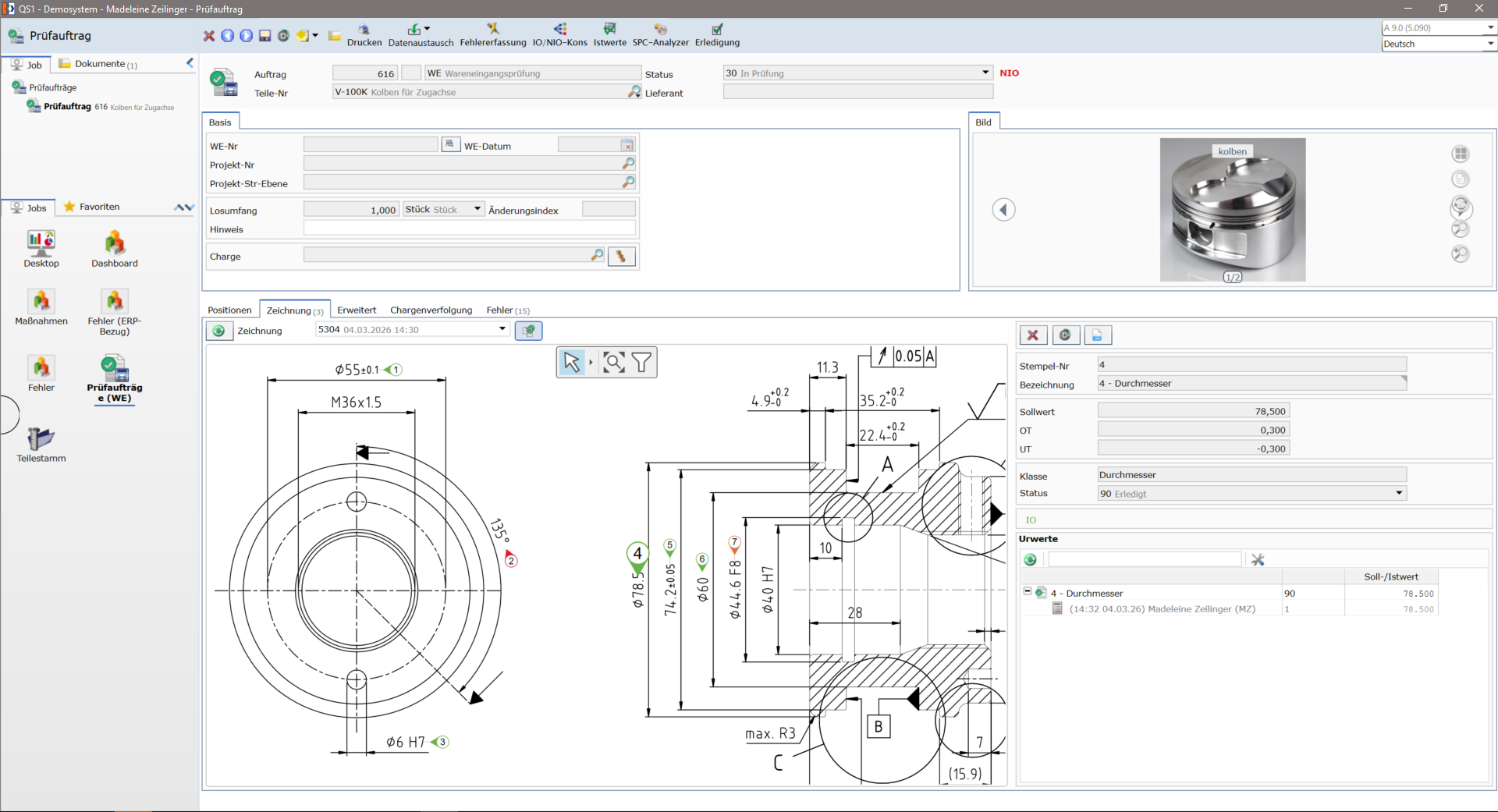
With QS1's CAD integration, you can create drawing-based inspection plans by digitally "stamping" the relevant dimension points. Instead of manually creating inspection features, a single click on the corresponding dimension point in the drawing is all it takes – and the associated inspection feature is automatically generated in the inspection plan. Target values and tolerances are recognized from the drawing and transferred to QS1.
Even extensive inspection plans can be created in a very short time – consistently and with minimal errors.
An integrated CAD viewer allows you to open, scroll, and interactively use 2D drawings directly in QS1. Stamped features are visually highlighted and can be accessed with a click. This ensures that the relationship between the drawing and the inspection feature remains transparent at all times.
Inspectors can also navigate from stamp point to stamp point and record measurements directly at the respective feature.
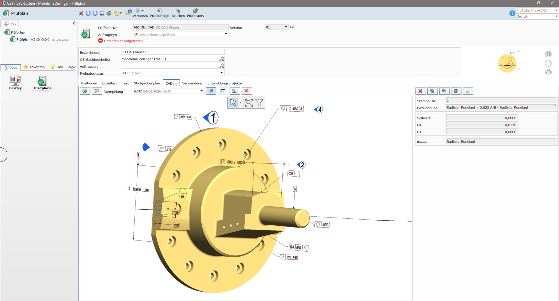
In addition to 2D drawings, an integrated 3D viewer is available. 3D models can be fully visualized, rotated, and analyzed. Inspection features can be stamped directly in the 3D model and later checked and reported back in the same view – including complete visual orientation to the component.
A convenient drawing comparison feature supports your version management. Inspection plan versions can be managed analogously to drawing versions.
For development-accompanying inspections, drawing stamping is also possible directly for the respective inspection orders, e.g., first article orders for tool release.
This creates a seamless, visual, and version-safe connection between design, inspection planning, and operational quality control.
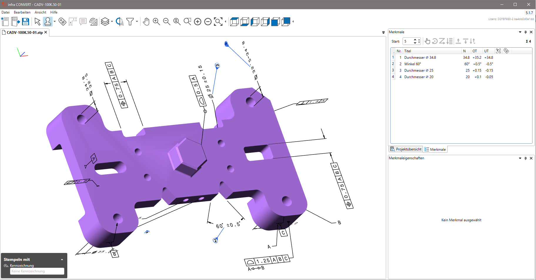
- Digital drawing stamping for initial sample inspections and inspection planning (e.g., VDA-compliant)
- Automatic recognition of nominal values, tolerances, fits, and form and position tolerances
- Use of existing CAD drawings and stampable PDF documents
- Support for 2D and 3D drawings with an integrated viewer
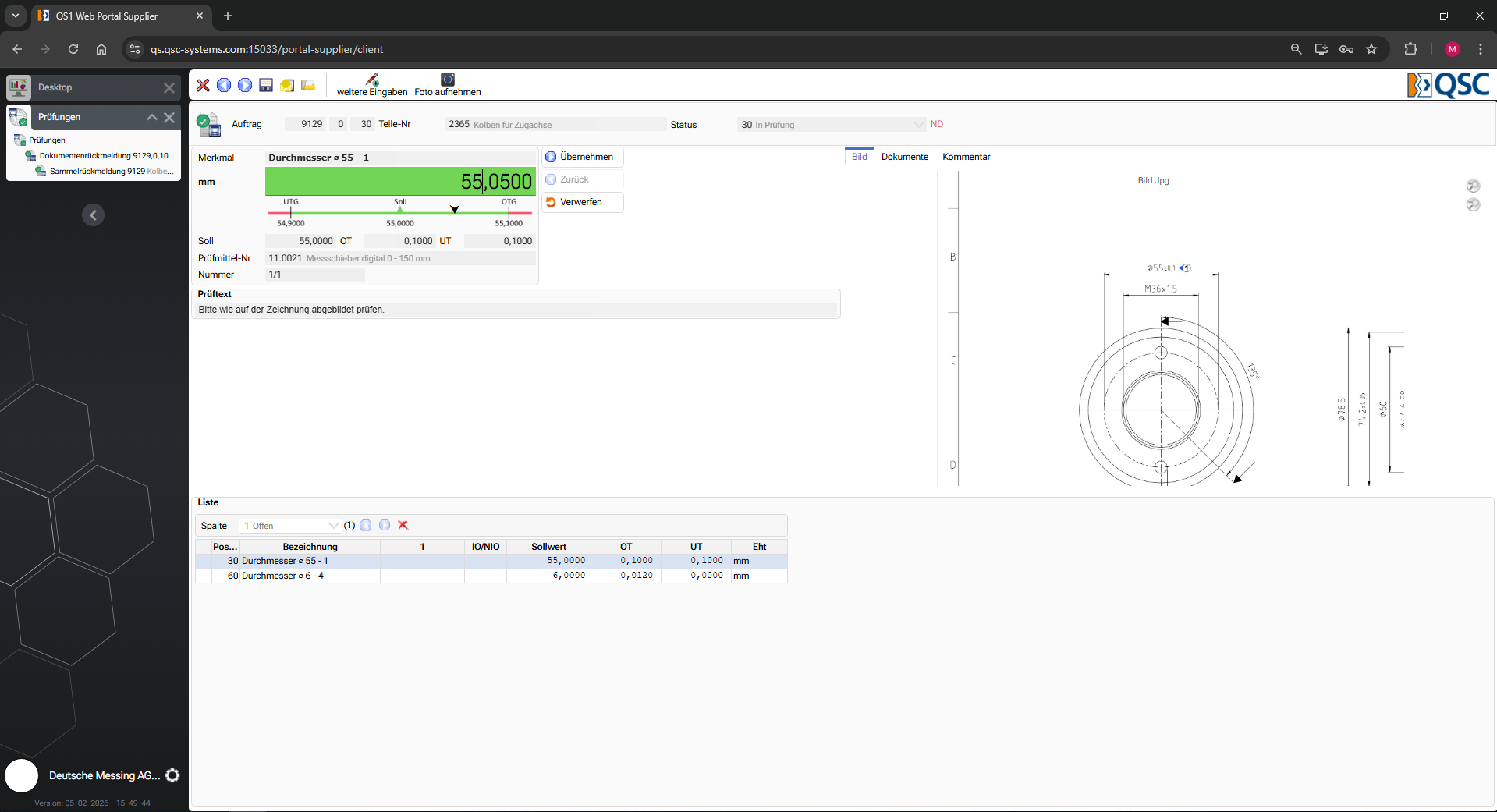
- Drawing-based inspection feedback directly at the stamping point
- Support for multi-page drawings, layout areas, and layers
- Attribute and variable features can be generated directly from the drawing
- Convenient drawing comparison for version changes
- Direct linking of dimension point and inspection feature
- Based on established CAD technologies from leading providers
- Reduction of manual transfer and input errors
Does this sound familiar?
- Drawing-based parts have many inspection features, but inspection planning is a tedious manual process: Dimensions are transferred, target values and tolerances are maintained separately, and errors creep in.
- Every time a drawing is changed, the process starts all over again: new dimensions, new tolerances, a new inspection plan version, and ultimately, it's unclear whether the inspection plan and drawing are truly synchronized.
- The relationship between drawing, dimension, and inspection feature is not readily apparent in daily practice: Measurements are taken, but without intuitive, visual guidance at the specific dimension point.
- Media breaks cost time: Drawings reside in separate tools, inspection plans in other systems, and feedback is stored elsewhere. This increases processing times and leads to transmission errors.
- Version management is cumbersome and audit-relevant: Which drawing version formed the basis of which inspection and which approval? Without a clean history, risky situations can quickly arise.
This should be achieved through a robust process
- Automated feature transfer from the drawing: Nominal values, tolerances, fits, and form and position tolerances must be converted into inspection features without manual input.
- Unambiguous, revision-proof linkage: Dimension point <=> inspection feature must remain permanently traceable (including versioning and history).
- Visual, guided inspection feedback: Inspectors must be able to navigate directly at the punch point and record measurements within the context of the component.
- 2D and 3D support: Drawings and models must be usable within the system (multi-page, layer/layout areas) without switching tools.
- Efficient change management: Drawing and inspection plan versions must be comparable and easily derivable so that changes can be quickly and reliably transferred to new inspection stations.
Coverage in QS1
- Creates drawing-based inspection plans through digital drawing stamping: A click on the dimension point automatically generates the corresponding inspection feature in the inspection plan without manual entry.
- Recognizes and adopts nominal values, tolerances, fits, and form and position tolerances directly from the drawing, significantly reducing data entry and transmission errors.
- Provides an integrated 2D viewer in which drawings can be opened, scrolled, and used interactively directly in QS1. Stamped features are visually highlighted and accessible with a click.
- Enables drawing-based inspection feedback: Inspectors navigate from stamp point to stamp point and record measurements directly at the respective feature. This leads to fast, reliable inspection processes.
- Additionally supports an integrated 3D viewer: Features can be stamped in the 3D model and later inspected and reported back in the same view with full visual orientation to the component.
- Ensures version management through drawing comparison and consistent inspection plan versions: Changes are transparently traceable, and inspection orders (e.g., initial sample orders for tool release) can be stamped directly on the drawing.
- Applicable with both existing CAD drawings and stampable PDF documents. Multi-page drawings, layout areas, and layers are also supported.
The result: Significantly faster test plan creation (up to a factor of 10), fewer transmission errors, a revision-proof connection between drawing and test plan, transparent change management and visually guided test feedback – all seamlessly from CAD to operational quality control.
Your Advantages
- Time savings of up to a factor of 10 in test plan creation
- Significant reduction in data entry and transmission errors
- Consistent and revision-proof link between drawing and test plan
- Maximum transparency in change management
- Accelerated test processes through visual navigation
- Efficient implementation of drawing changes
- Improved collaboration between design and quality assurance
- End-to-end digital process from CAD to test feedback
- Increased process reliability for initial sample inspections and series production tests
